
Pillbox antenna for ADS-B 1090MHz reception
Pillbox antenna for ADS-B reception at 1090MHz, started as proof of concept design, gone through 3D modeling and optimization and final measurements on a prototype built.
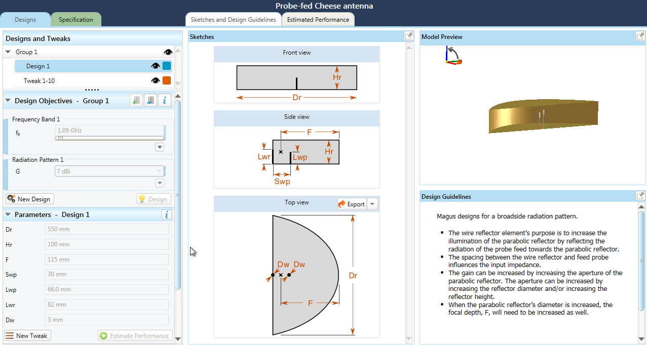
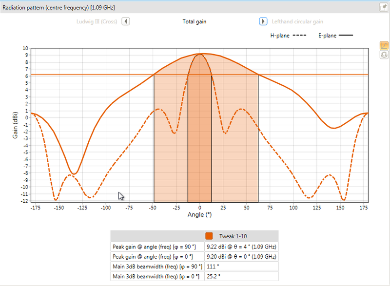
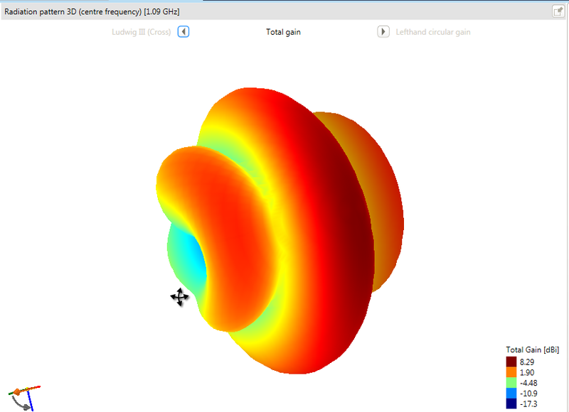
Theory #
Concept and initial design in Antenna Magus (where it's called a probe-fed cheese antenna)
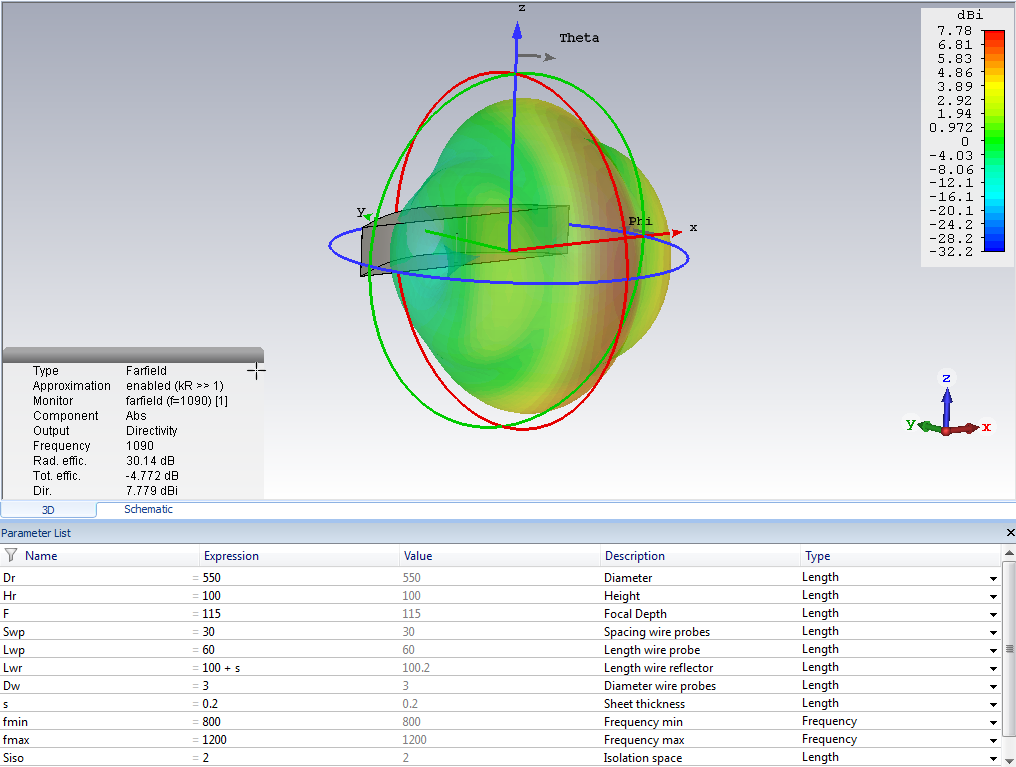
Simulation in CST
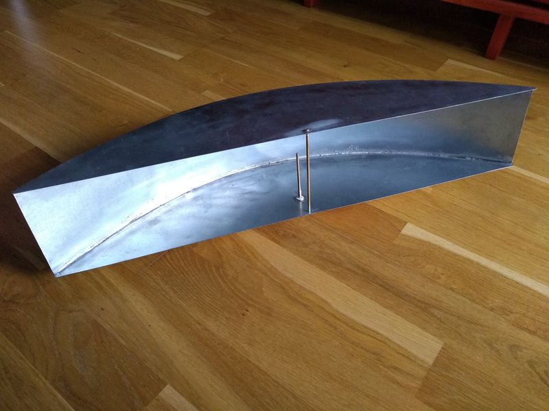
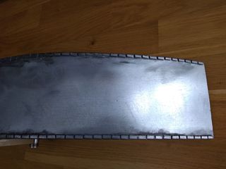
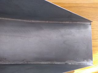
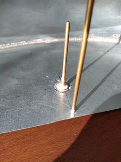
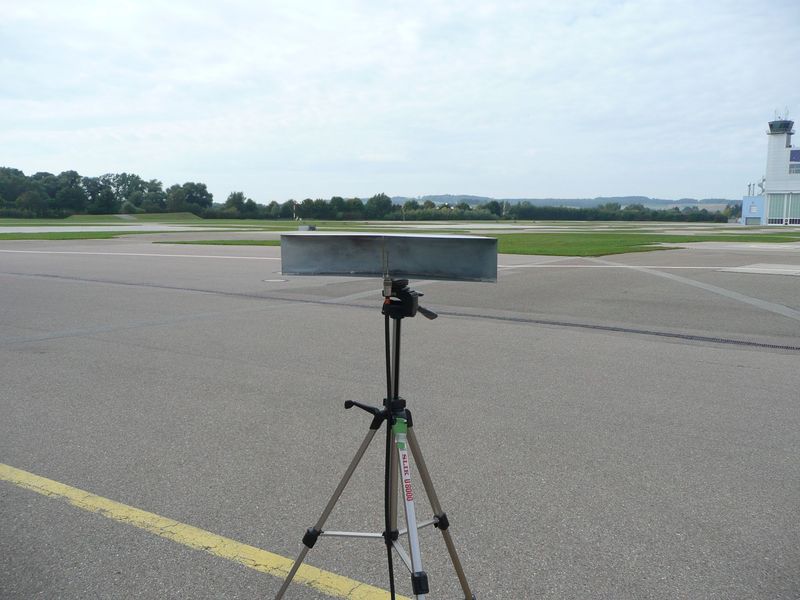
Reality #
Final build dimensions
- Diameter Dr: 550 mm
- Height Hr: 100 mm
- Focal depth F: 115 mm
- Spacing wire probes Swp: 30 mm
- Length feeder probe Lwp: 60 mm
- Length reflector Lwr: 100 mm
- Wire diameter probes Dw: 3 mm
- Sheet metal: calvanized steel, thickness 0.2 mm
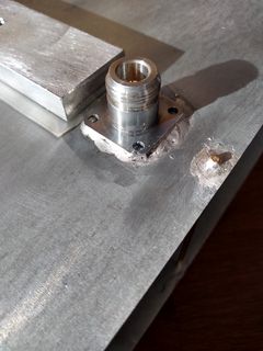
- Feed probe and reflector: 3mm brass tube
- Feed socked: N type flange mount
Download drawing for top and bottom sheet.
See drawing for reference.
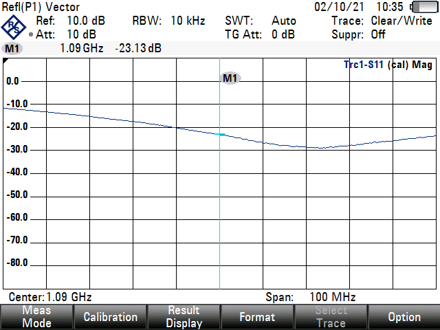
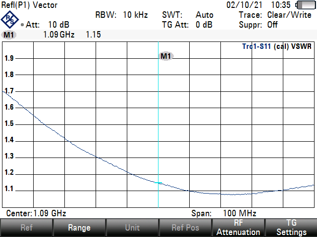
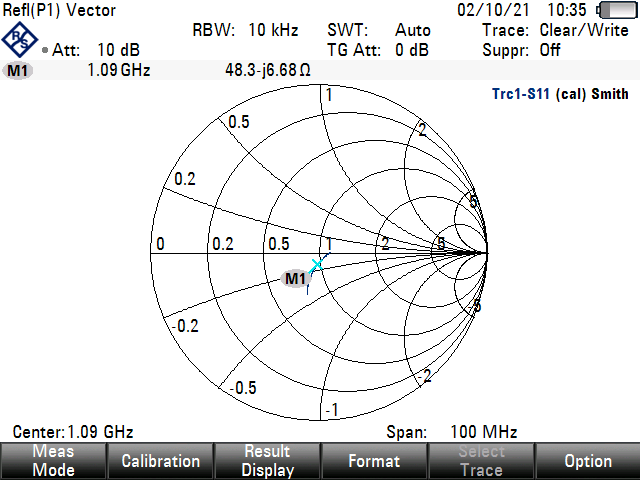
Impedance measurement results #
Gain measurement results at 1090 MHz #
The directivity gain has been measured using the gain transfer method.
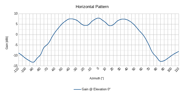
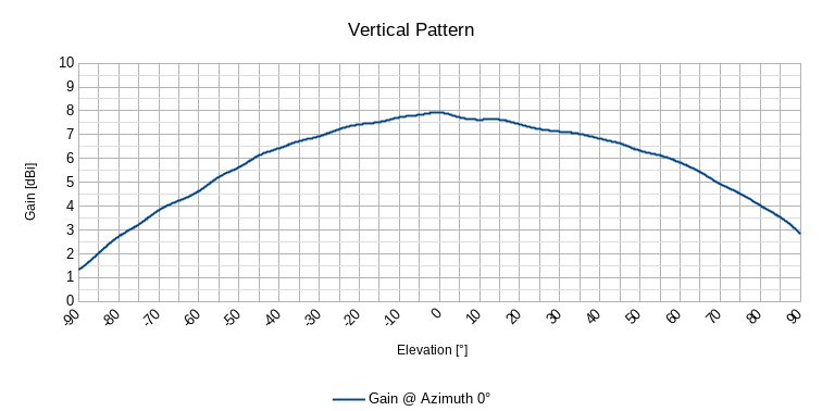
- Maximum directivity gain 7.93 dBi at azimuth 0° and elevation 0°
- Main 3 dB horizontal beam width (elevation 0°): ~27°
- Side lobe 3 dB horizontal beam width (elevation 0°): ~99°
- Main 3 dB vertical beam width (azimuth 0°): ~128°
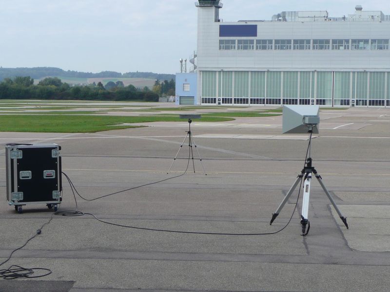
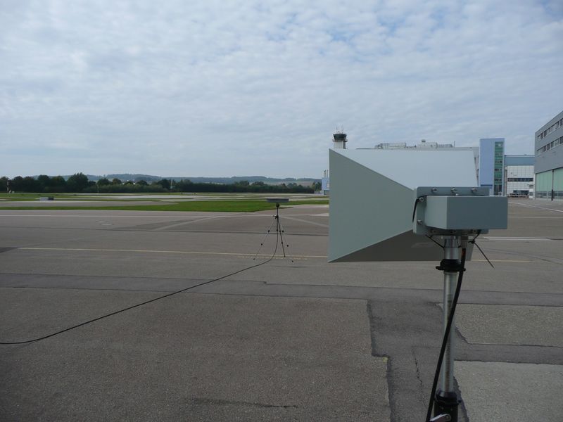
Test setup:
- Test antenna: AINFO Octave Horn Antenna LB-OH-650-15-C-NF 1.0-2.0 GHz
- Reference antenna: Schwarzbeck RS-0460, 0.53 dBi @ 1090 MHz
- Test receiver with tracking generator: R&S ESRP7, RF output power 0 dBm
- Distance test antennas: 10 m (far field conditions)
- Azimuth test range: -110° to 110° @ elevation 0°
- Elevation test range: -90° to 90° @ azimuth 0°
👈 Home