
How To Measure Antenna Gain - Gain Transfer Method
This page archives the article that was posted first on http://www.measurementest.com/2010/09/how-to-measure-antenna-gain-part-1-gain_08.html. The website doesn't exists any longer.
Gain is one of the key specifications in antenna datasheets. It is defined as the ratio of the intensity of an antenna (usually in direction of peak radiation) relative to an isotropic antenna. This is the reason why the antenna gain is specified as dBi in antenna datasheets - dB refers the ratio or gain and i signifies relative comparison to an isotropic antenna. An isotropic antenna is a hypothetical antenna that radiates with equal intensity in every direction without any losses.
Having sufficient gain is crucial to successfully send any RF/Microwave signals over the air. Too little of it will cause the signal to fade away before reaching its destination. Too much of it will cause distortion products in your receiver. Hence, antenna gain is an important parameter in helping us to plan or design wireless transmission link budget.
There are several ways to measure antenna gain and will be covered in several parts. This being the first part, will cover the gain-transfer method which is also known as gain-comparison method. According to IEEE Standard Test Procedures For Antennas, ANSI/IEEE Std 149-1979, this is the most commonly employed method for antenna power-gain measurement.
The gain-transfer method requires 3 antennas - 1 AUT, 1 reference and 1 don’t care. The AUT or antenna under test is the one which we are interested in finding out the gain. The reference antenna is the one which the gain () is accurately known, has a high degree of dimensional stability and polarization purity. It is used as a benchmark. The don’t care antenna is basically an antenna which we do not need to know the gain exactly, but it must at least have sufficient dynamic range to transmit all the way to the AUT.
For this purpose, we can consider several types of instrument choices:
- Vector/scalar network analyzer
- Spectrum analyzer with tracking generator or separate signal generator
- Power meter and signal generator
However, for convenience and ease of use, we will take a look how to measure antenna gain using a network analyzer because a network analyzer typically comprises of both source and receiver.
Here are the suggested steps:
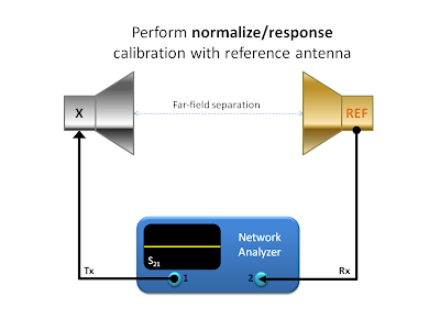
- Mount the don’t care (we just call it X) and reference antenna on a stable tripod/holder.
- Have a far-field separation between the antennas.
- Connect the X antenna to port 1 (transmitter) of the network analyzer and reference antenna to port 2 (receiver).
- Ensure the antennas are well aligned in terms of polarization and direction of maximum radiation intensity.
- Activate the S21 measurement.
- Set the frequency range of interest on the network analyzer.
- Optimize the dynamic range (more details of this will be covered in another post).
- Perform response/normalize calibration which should produce a flat S21 response at 0 dB across the selected frequency range. This means that the gain is now normalized to the reference antenna.
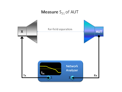
- Replace the reference antenna with the AUT at the exact position and alignment.
- Record the new S21 values. This is the gain/loss of the AUT relative to the reference antenna. Let’s denote this as GRelative.
- The gain of the AUT, GAUT is then determined by the following equation at every frequency point:
= +
Let’s put in some numerical example to better understand this equation by considering the antenna gain chart in Figure 1. Assuming we’re interested in the frequency point of 7 GHz, we can obtain a GRef = 10 dBi from Figure 1.
Imagine that you obtained an AUT S21 value of -3 dB at 7 GHz from the network analyzer. This gives us
Therefore,
In words, the AUT has a 3 dB lower gain compared to the 10 dBi of the reference antenna at 7 GHz. Therefore the gain of the AUT in dBi must be 7 dBi.
To improve measurement setup and results, here are some recommendations:
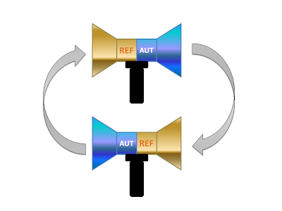
- Use identical antennas for X and REF. This makes it easier to align and match the antennas together. Better still if they are physically similar to the AUT.
- Put the AUT and REF antenna back to back with the ability to swivel them 180 degrees, so it’s easier for the AUT to be in the exact position of the REF after the switch.
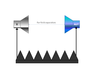
- Make measurements with absorbers placed below the antenna to reduce ground reflection, or better still, perform this in an anechoic chamber.
This method has been used to measure the gain of my Pillbox antenna for ADS-B 1090MHz.
👈 Home