
Laser distance meter hack
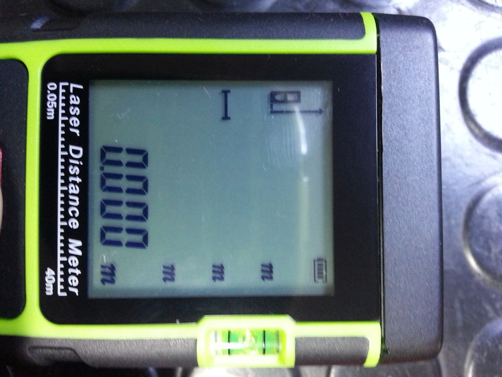
I'm finally hacked a cheap laser distance meter from Amazon. Arduino Mini is taking control. Someone else tried before but gave up on this. Mine looks the same like the KKMOON but has no brand marking.
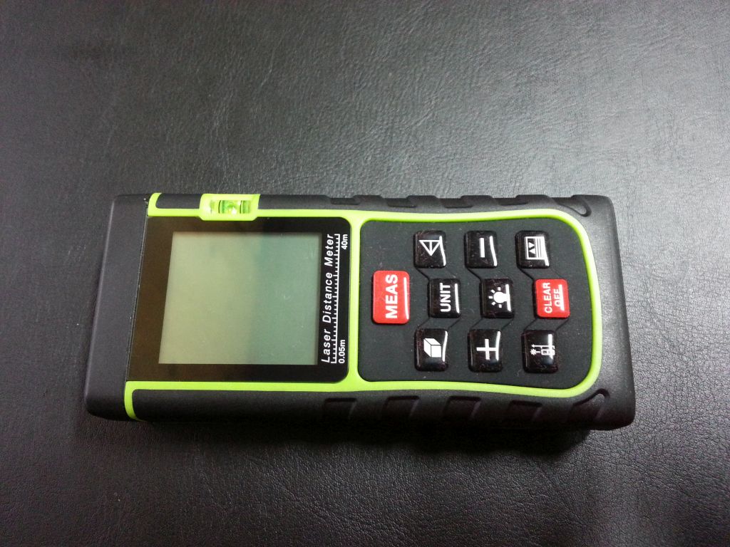
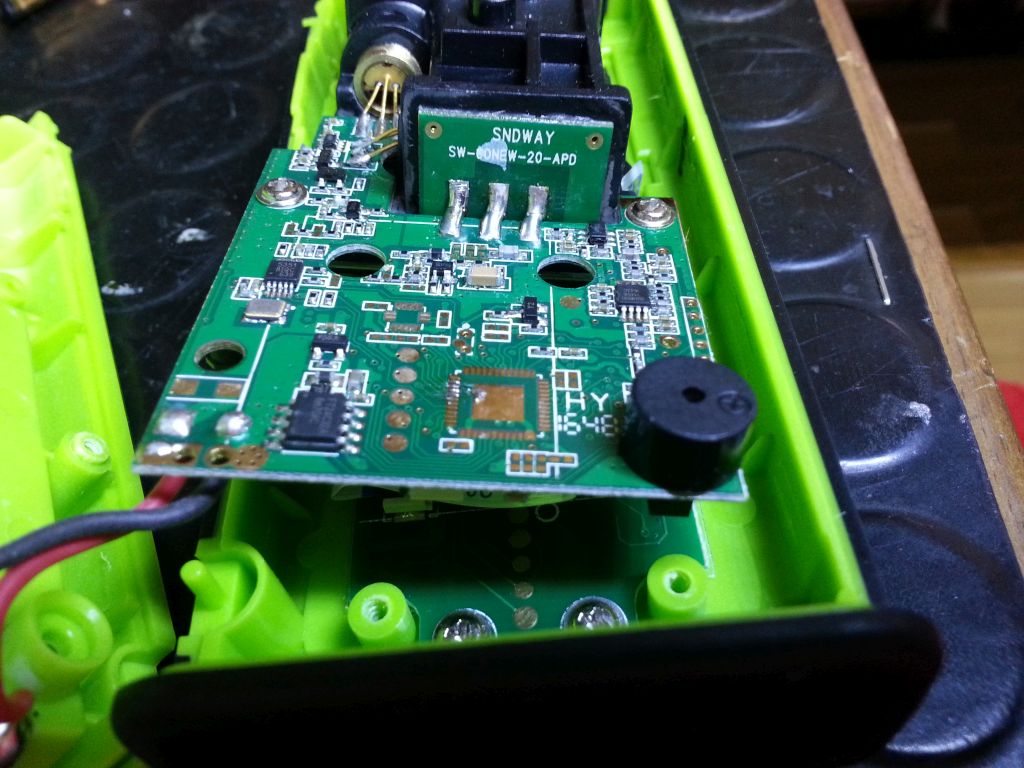
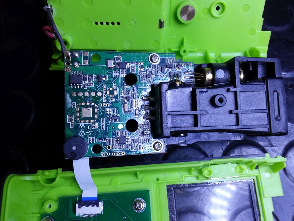
Taking the laser distance meter apart.
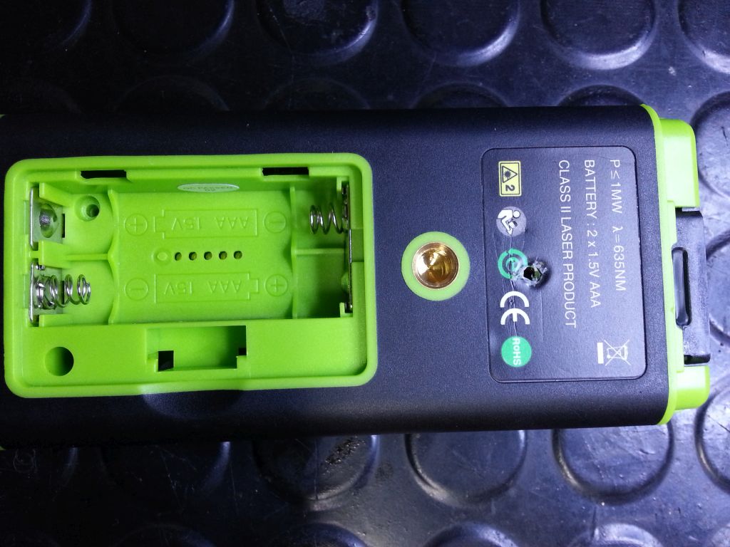
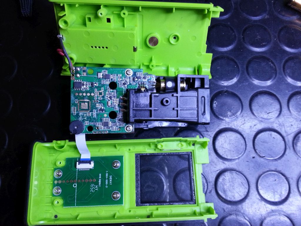
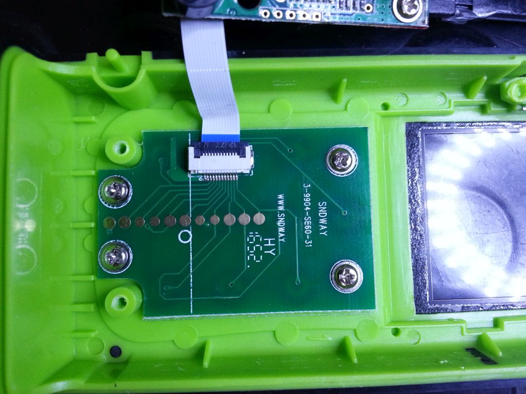
While there are no outside markings, the inside reveals the manufacturer - SNDWAY. Seems to be an SW-A40.
Hackaday.io has a description of several pads on the main board.
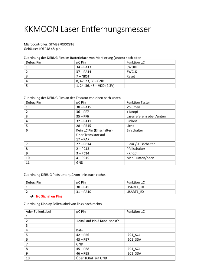
The keypads on my device main board are different to the description above.
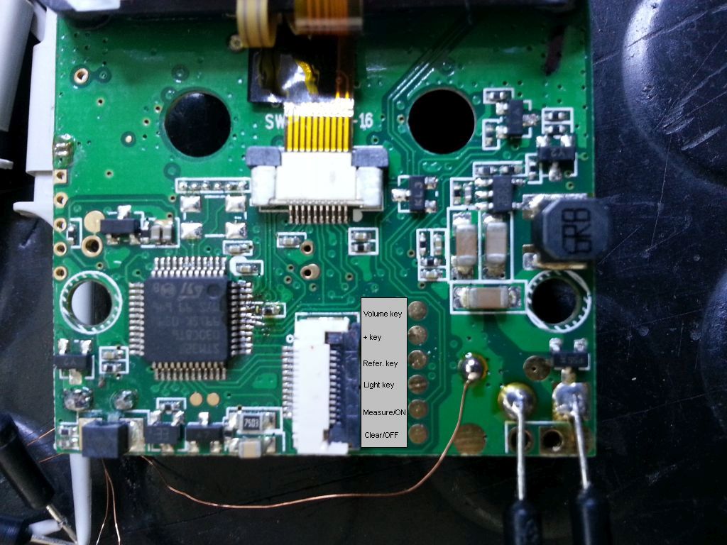
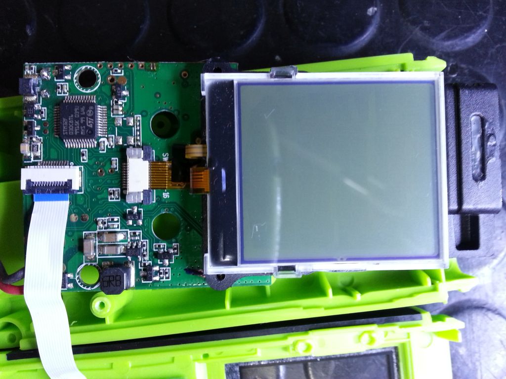
Debugging pads on the main board backside providing acces to the STM32 SW debug port. I tried with an ST-Link V2 just to find the chip being locked in protection level 1. So one can not read the firmware. However, there are two chips missing on the main boards back side. So I probed the with an oscilloscope. Found three pins with activity on which is an unidirectional SPI bus.
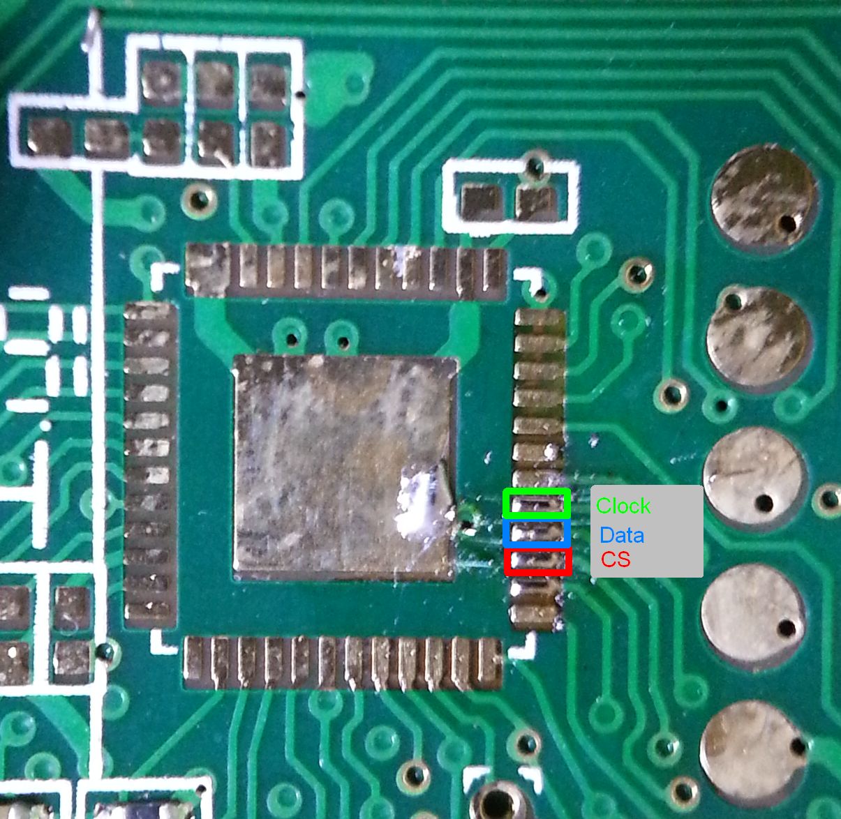
Details about the bus that I found so far:
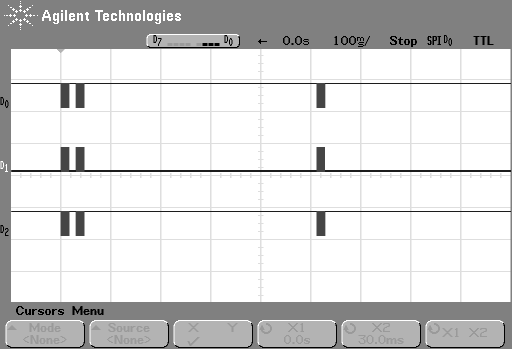

- Signal level is 0V to 3V.
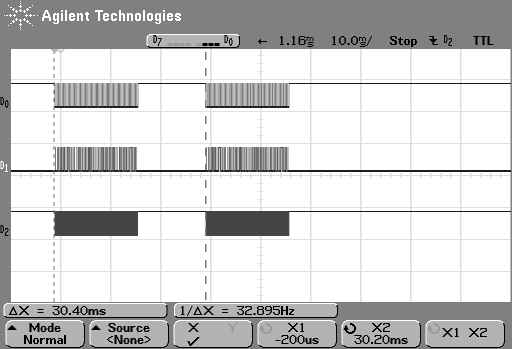
- Clock frequency 37KHz.
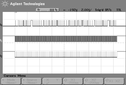
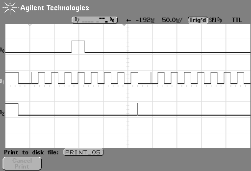
- The are 8 long clock pulses and one short pulse for each byte. Data is LOW in first, second and third byte of each sub-frame during this short pulse (byte data is a command). For any other byte in sub-frames DATA is HIGH during this short pulse (byte data are LCD symbols).
- Data sampling at rising clock edge.
- Bit order seems to be MSB first.
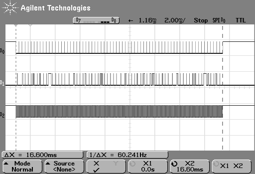
- CS signal (D2 in above plots) is high when bus inactive, there is a short strobe pulse at the end of each byte.
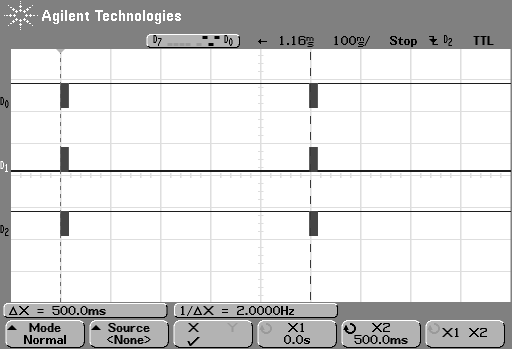
- In continuous measurement mode the main frame is randomly split and the 17 bytes sub-frames are transmitted with a pause in between. Obviously a timing issue when the controller is busy while measuring distance.
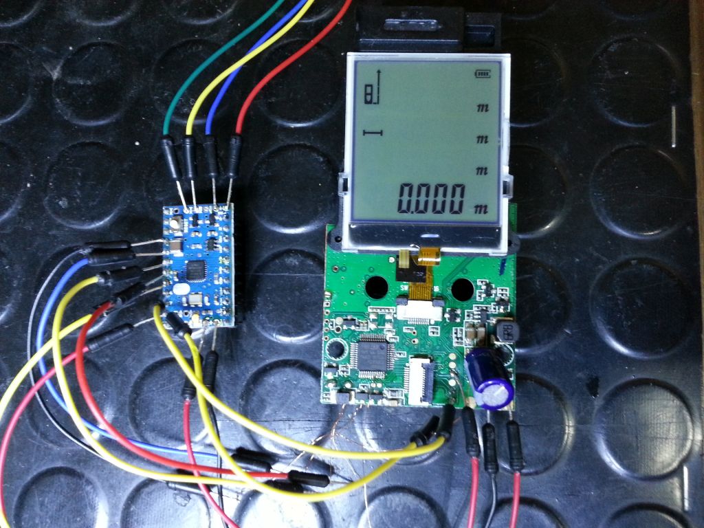
Before you connect any hardware to the LCD bus of the laser distance meter make sure it runs at 3V signal levels! The Arduino Mini by default is not! Solutions are either level converters or, what I did, simply exchange the linear voltage regulator IC1 on the Arduino Mini board to an 3V version.
Running the Arduino Mini at 3V brings also the advantage that you can power the device main board directly from the Arduino Mini. Doing so requires an additional capacitor of at least 1000uF/6.3V connected to the power input (where the battery wires were connected) to buffer any power surge when the device and laser will be switched on.
Next I coded a quick and dirty sketch for a Arduino Mini board. It uses the circular buffer library from https://github.com/rlogiacco/CircularBuffer.
This code reads two frames then sends them via serial interface. It ignores the very first short pulse leading each data byte. The result looks like this:
10 00 C0 00 00 0A 00 02 00 00 05 58 00 00 00 00 00 10 01 C0 00 00 06 00 02 00 00 03 F0 00 00 00 00 00 10 02 C0 00 00 02 00 02 C0 00 C5 70 00 00 40 00 00 10 03 C0 00 00 00 00 42 00 00 07 58 60 00 06 00 00
10 00 C0 00 00 0A 00 02 00 00 05 58 00 00 00 00 00 10 01 C0 00 00 06 00 02 00 00 03 F0 00 00 00 00 00 10 02 C0 00 00 02 00 06 C0 00 C5 70 00 00 40 00 00 10 03 C0 00 00 00 00 42 00 00 07 50 60 00 06 00 00
10 00 C0 00 00 0A 00 02 00 00 05 58 00 00 00 00 00 10 01 C0 00 00 06 00 02 00 00 03 F0 00 00 00 00 00 10 02 C0 00 00 02 00 02 C0 00 C5 70 00 00 40 00 00 10 03 C0 00 00 00 00 42 00 00 07 58 60 00 06 00 00
Each 68 bytes frame contains 4 sub-frames of 17 bytes starting with:
10 00 C0
10 01 C0
10 02 C0
10 03 C0
These are command bytes (first bit = 0) while the remaining 14 bytes are LCD data (first bit = 1). This bus is driving the LCD.
2F 34 B1 1E B2 0F 14 A0 94 68 3D 88 88 88 88 60 E3
10 00 C0 FF FF FF FF FF FF FF FF FF FF FF FF FF FF 10 01 C0 FF FF FF FF FF FF FF FF FF FF FF FF FF FF 10 02 C0 FF FF FF FF FF FF FF FF FF FF FF FF FF FF 10 03 C0 FF FF FF FF FF FF FF FF FF FF FF FF FF FF
10 00 C0 FF FF FF DF FF FF FF FF FF FF FF FF FF FF 10 01 C0 FF FF FF F7 FF FF FF FF FF FF FF FF FF FF 10 02 C0 FF FF FF FB FF FF FF FF FF FF FF FF FF FF 10 03 C0 FF FF FF F3 FF FF FF FF FF FF FF FF FF FF
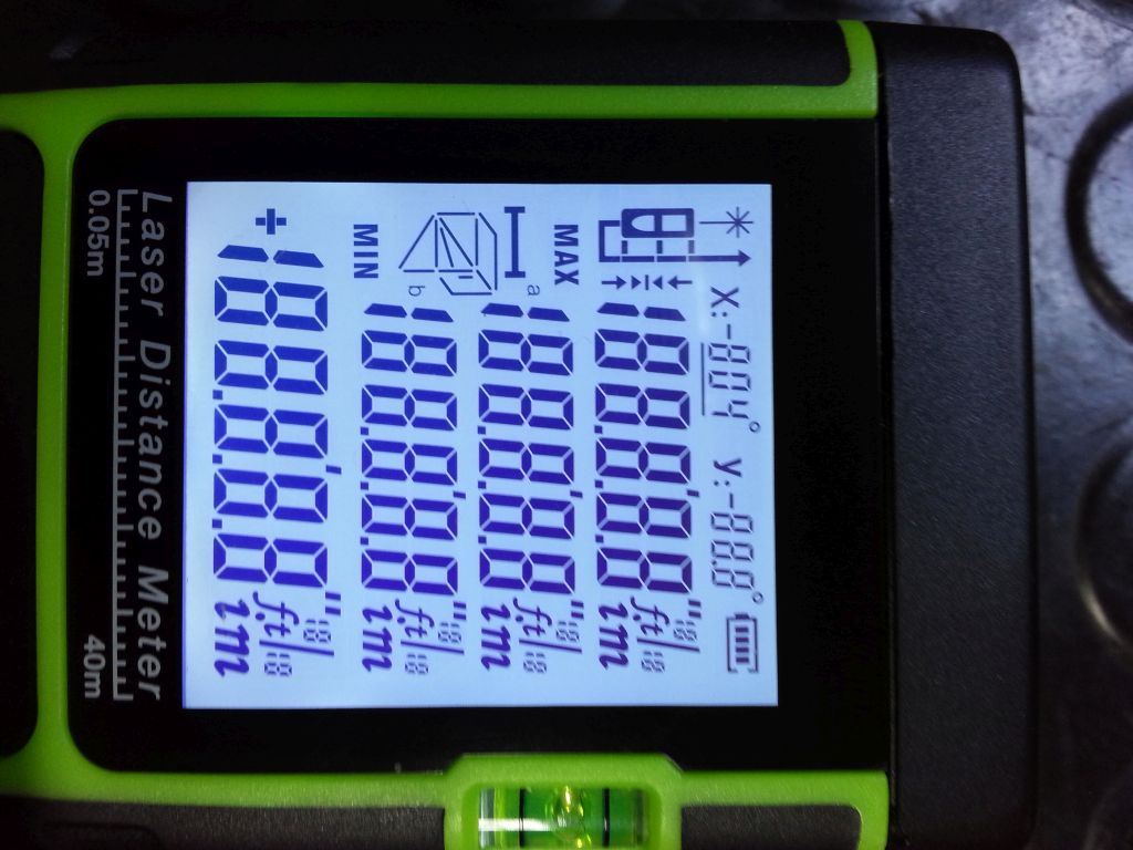
First line is configuration data for the LCD driver while the two lines with all byte 0xFF are showing all the LCD segments and symbols that we can see for a short moment on the power on screen.
The following sub-frames are showing all symbols of the lowest LCD line, where the actual measured distance is shown including its unit.
10 00 C0 00 00 00 00 00 00 00 FF FF 00 00 00 00 00
10 01 C0 00 00 00 00 00 00 00 FF FF 00 00 00 00 00
10 02 C0 00 00 00 00 00 00 00 FF FF 00 00 00 00 00
10 03 C0 00 00 00 00 00 00 00 FF FF 00 00 00 00 00
So we can break down the distance look-up process into 2 bytes per sub-frame, 8 bytes in total or 64 bit. The look-up table for each number per digit, sign and unit is available for download below.
This Arduino code will simply read out the distance and sends via serial interface.
Final code to control and read the SW-A40 laser distance meters.
👈 Home