
Sleeve dipole antenna for Meshtastic at 869MHz - Version 2
Sleeve dipole antenna for Meshtastic operation at 869MHz. Version 2 step by step DIY build instruction
That's my fifth antenna built of this kind. The results are reliably and repeatable. Its performance exceptional. I'm replacing all the COTS antennas on my Meshtastic node by this DIY version.
Bill of Material #
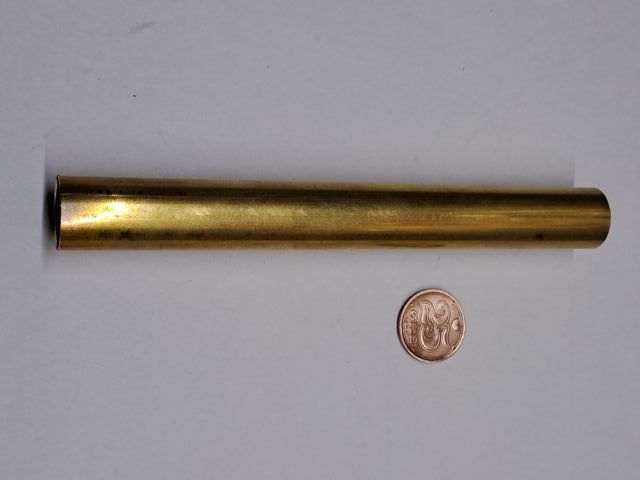
- Brass pipe, outer diameter 15 mm, inner diameter 14 mm, length >75 mm (sleeve)
- Brass pipe, outer diameter 2 mm, inner diameter 1.4 mm, length > 85 mm (radiating rod)
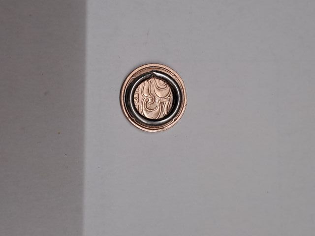
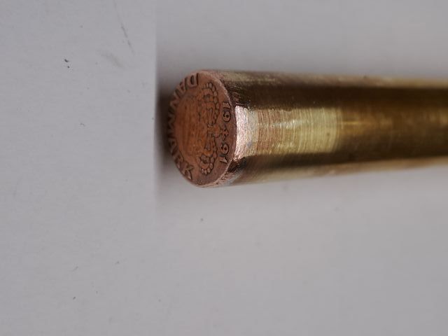
- Coin, outer diameter >15 mm, e.g. 0.01€, 0.25 Danish Krone (sleeve end cover)
- PVC/Vinyl pipe, outer diameter 20 mm, inner diameter 18 mm, length >180 mm
- PVC/Vinyl sheet, thickness 2-3 mm
- Foam for spacer
Semi-rigid coax might be expensive and not easy to source. A cheap solution is a combination of RG-316 inside a brass pipe. Either including the shielding or just the inner conductor with isolation. (with shield recommended)
Dimensions #
Final build dimensions
- Sleeve length: 75 mm
- Sleeve outer diameter: 15 mm
- Sleeve inner diameter: 14 mm
- Sleeve material: Brass
- Semi-Rigid Coax type: UT-141C / SR141CUTP / RG402
- Semi-Rigid outer diameter: 3.6 mm
- Semi-Rigid conductor diameter: 0.92 mm
- Semi-Rigid total length: ~100 mm
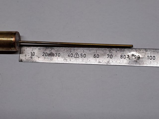
- Radiator length: 85 mm
- Feed socked: SMA type flange mount for UT-141C / RG402
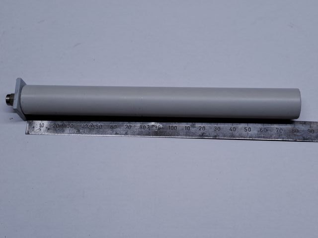
- Protection pipe outer diameter: 20 mm
- Protection pipe inner diameter: 18 mm
- Protection pipe length: 180 mm
- Protection pipe material: PCV/Vinyl
Build steps #
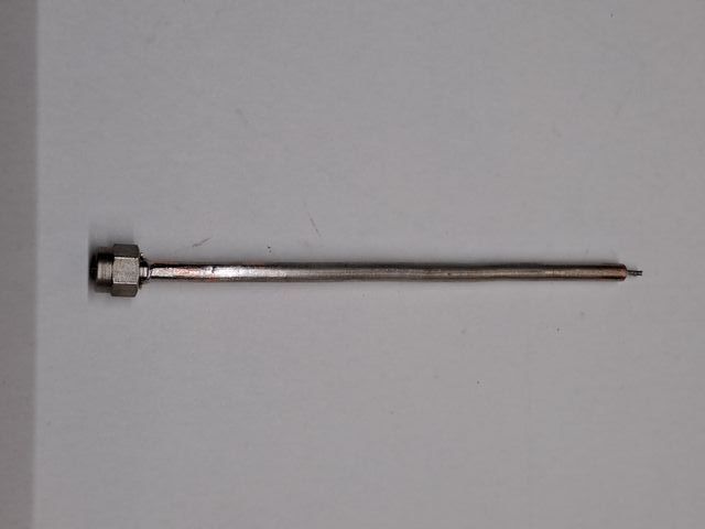
1 - Feeding coax #
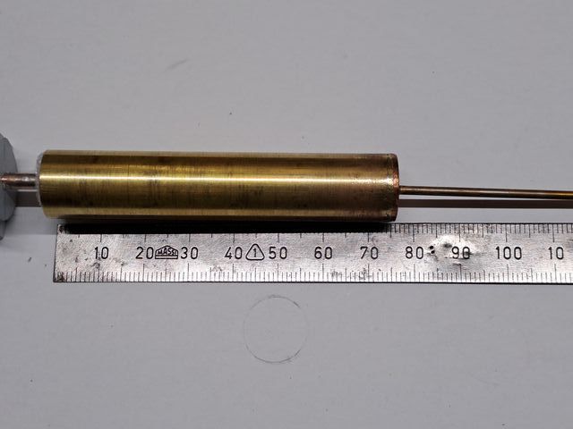
2 - Sleeve build #
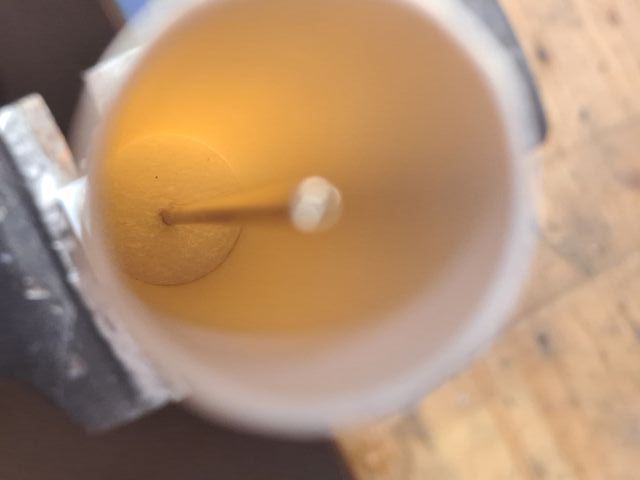
3 - Prior assembly #
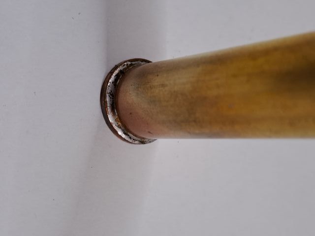
The coin cover is drilled and counter sunk to increase the solder area.
Lower foam spacer with inner diameter of sleeve pipe. (14 mm)
The bottom cover for the protection pipe is made of two glued layers PVC/Vinyl. Drilled to size for the semi-rigid coax. The round part fits inside the protection pipe (diameter 18 mm) while the square part is a bit oversized (22x22 mm) to the protection pipe outer diameter. Will be trimmed when finally glued.
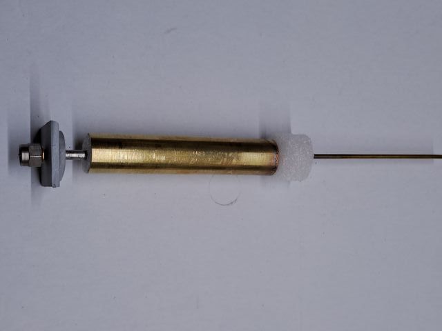
4 - Feed point soldered #
Coax inner isolation is cut flush with the coin cover.
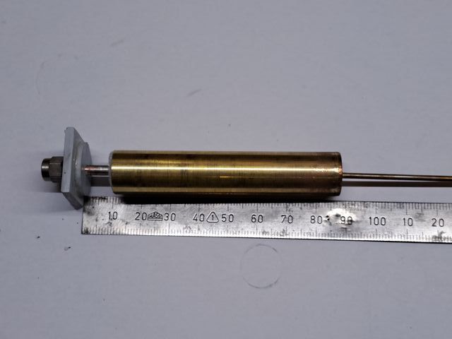
5 - Completely assembled #
Middle foam spacer diameter equals the inner diameter of the protection tube. (18 mm)
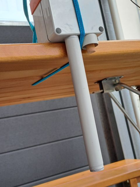
6 - Antenna placed in protection pipe #
Protection pipe will be glued to its bottom cover after impedance measuring and tuning.
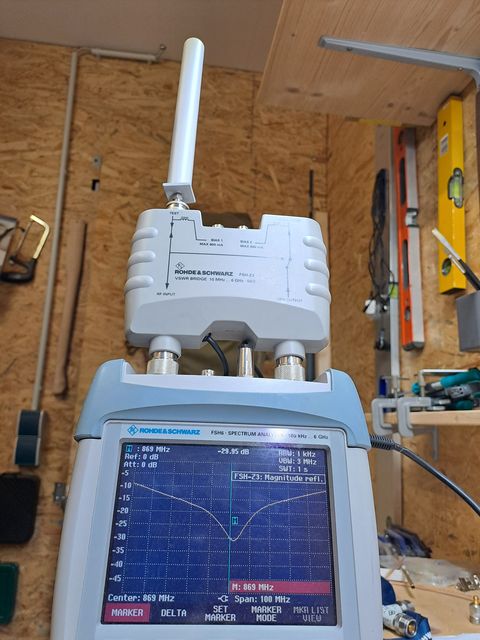
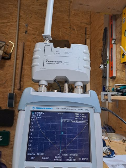
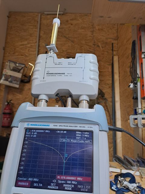
7 - Impedance measurement results #
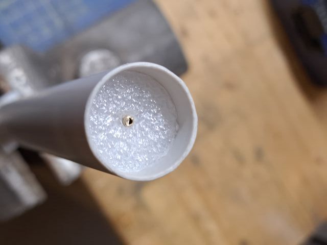
8 - Top prior closing #
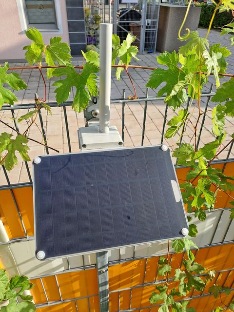
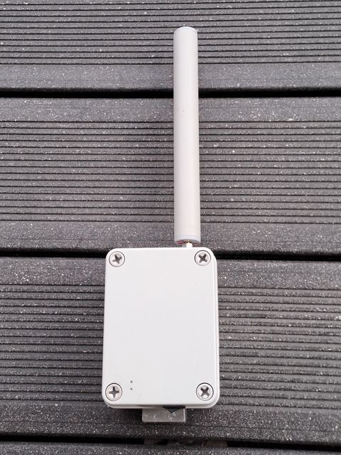
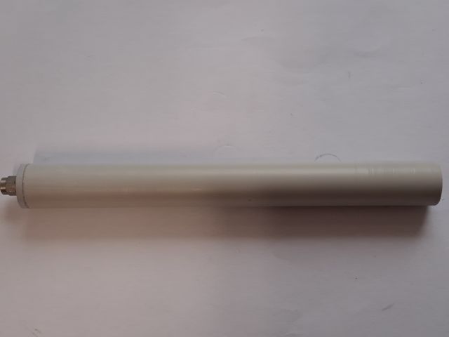
9 - Final antenna #
Dimension details #
👈 Home