
From Nokia 5130 to Meshtastic 5130
A summary about the conversion of an old Nokia 5130 mobile phone into a modern Meshtastic node. Retro tech wizardry at its best.
How it started #
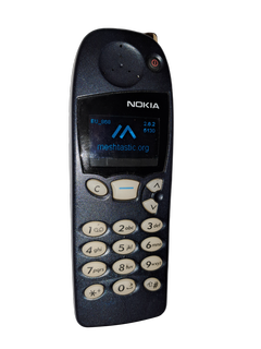
The idea came with an old Nokia 5130 phone that spent more than 20 years in a drawer. Still nice looking, too good to throw away.

How it ended #
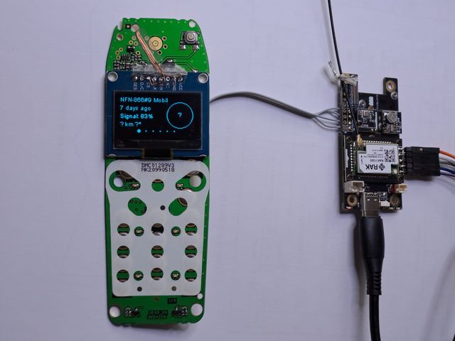
- 1.3inch OLED display
- Fully functional T9 style keypad for individual or canned messaging
- Power button for reboot and shutdown
- USB-C charging and serial debug interface, firmware upload in bootloader mode
- SMA antenna connector
- Nokia 5130 compatible battery usage
- Bluetooth connection to Meshtastic app
- Visible RAK19007 WisBlock LEDs
Parts #
Meshtastic firmware is plays nice with the following components inside the Nokia 5130 housing:
- RAK19007 WisBlock Base Board 2nd Gen
- RAK4631 Nordic nRF52840 BLE Core Module for LoRaWAN with LoRa SX1262
- RAK12002 RTC Module Micro Crystal RV-3028-C7
- RAK1906 environment sensor Bosch BME680
- Waveshare 1.3inch OLED (A)
- Adafruit TCA8418 Keypad Matrix and GPIO Expander Breakout
The following parts have been reused from the Nokia 5130:
- Housing front (A cover)
- Housing inner (B cover)
- Housing rear (C cover)
- Keymat
- Keypad PCB (UI module UE4S), excluding LCD
- Main PCB (System/RF Module UP8T, all components stripped except battery connectors)
- Inner PCB separation frame
- Screws
Conversion #
This is not a detailed build manual but showing the idea and the way I have done it in that individual built. A schematic is provided down below.
- The RAK19007 can be equipped with a core module RAK11300 but in this case the Bluetooth feature is missing and the power consumption is way higher than with the RAK4631.
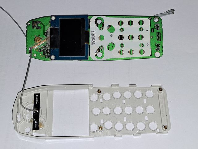
- The Waveshare 1.3inch OLED is connected to the Adafruit TCA8418 with enamelled copper wire. Taking power (3.3V, GND) and I2C.
- The 6 LEDs for the original LCD display must be removed prior OLED assembly.
- The TCA8418 keypad driver is connected with enamelled copper wire to the Nokia UI module.
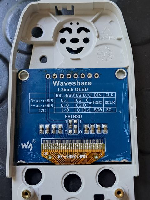
- The Waveshare 1.3inch OLED needs trimming at the bottom but otherwise fits perfectly inside the inner B cover.

- The Nokia rear housing C cover was modified by filling the external antenna hole and the Nokia logo with epoxy.
- Three extra holes drilled to fix the RAK19007.
- The original connector block was removed from the main PCB, its contacts removed and and glued in its designated place. All caps and openings filled with epoxy.
- The SIM card slot opening is not yet covered in this picture. A piece of PVC plastic was glued in in the final assembly stage prior painting.
- The two screw holes on the right are closed in this picture but later on reopened to fix the inner B cover in place.
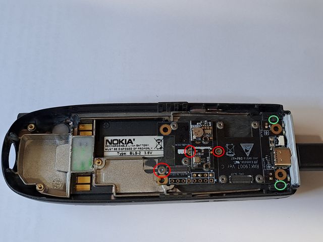
- Inside the rear housing C cover the antenna location was trimmed to take a long SMA socket with IPX pigtail.
- The lower end, including the original connector block, was trimmed inside to make space for the RAK19007.
- A 3mm PVC plastic strip was glued in place, drilled and shaped to accept the USB-C connector, access the reset button and make the LEDs visible outside.
- Red circles marking the screws are fixing RAK19007 inside the housing.
- Green circles are the two existing screw holes for the inner B cover. They are barely fit without modification to the RAK19007 PCB.
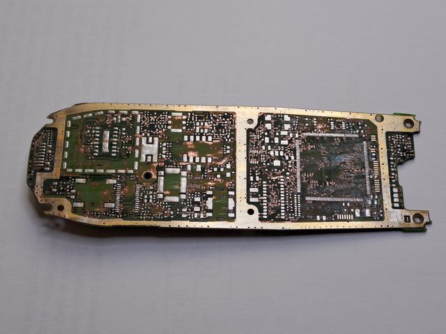

- The main PCB stripped off its components except the battery contacts.
- Needs to be reused for to contact the battery and to complete the original sandwich assembly of both PCBs and separation frame.


- The main PCB needs a cutout to clear the RAK19007 including core and extension boards.

- The bluetooth antenna just clears the Waveshare OLED display in the location.

- I2C wiring and bluetooth antenna cable are routed below the separation frame through a cutout.
- In this picture the separation frame is not yet trimmed to clear the RAK19007 and RAK4631 core board.

Assembly #


- Power supply wires soldered to battery contacts prior assembly of main PCB into rear housing C cover.
- Main PCB is fixed with its original screw to the rear housing. (red circle)

- UI PCB is fixed with two original screws to the rear housing. (red circles)
- The inner housing B cover is fixed by the two original lower screws from the back side of the rear housing C cover. (green circles)
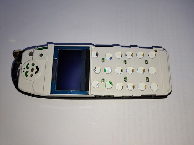
Complete #

- In this picture the three screws that fix the RAK19007 are visible.
- The SIM card slot is closed with a piece of PVC plastic, glue in place.
- The two lower screws that fix the inner housing B cover are still missing. They were installed as one of the last steps.


- Any Nokia 5130 compatible covers and keymats can be used with that built.

- The keys backlight is activated on tap any switched off after 2 seconds of inactivity.


- Keypad works in T9 style.
Mission accomplished.😎
Schematic #


| Pin | Line Symbol | Parameter | Connect to TCA8418 |
|---|---|---|---|
| 1 | ROW0 | Keyboard matrix row 0 | R0 |
| 2 | ROW1 | Keyboard matrix row 1 | R1 |
| 3 | ROW2 | Keyboard matrix row 2 | R2 |
| 4 | ROW3 | Keyboard matrix row 3 | R3 |
| 5 | ROW4 | Keyboard matrix row 4 | R4 |
| 6 | COL0 | Keyboard matrix column 0 | C0 |
| 7 | COL1 | Keyboard matrix column 1 | C1 |
| 8 | COL2 | Keyboard matrix column 2 | C2 |
| 9 | COL3 | Keyboard matrix column 3 | C3 |
| 10 | COL4 | Keyboard matrix column 4 | C4 |
| 11 | Signal1 | Flip interrupt, not used | |
| 12 | VF_IN | Flash in | |
| 13 | VF_OUT | Flash out | |
| 14 | VBATT | Battery voltage 3.0V to 5.1V for lights 60-100mA | 3.3V |
| 15 | UAGND | Analog ground, connect to pin 22 | GND |
| 16 | PWRON | Power on key | C5 |
| 17 | LCDCDX | LCD driver code/data selection | |
| 18 | SCLK | LCD driver serial clock | |
| 19 | SDA | LCD driver serial data | |
| 20 | LCDCSX | LCD driver chip select | |
| 21 | LCDRSTX | LCD driver reset | |
| 22 | UDGND | Digital ground, connect to pin 15 | GND |
| 23 | BUZZER | Buzzer PWM control | |
| 24 | VL | Supply voltage | |
| 25 | SPARE | Call indicator LED | |
| 26 | LIGHT | Illumination control | C9 |
| 27 | EARN | Speaker neutral | |
| 28 | EARP | Speaker positive |
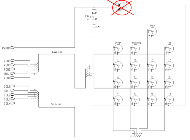
- Diode V27 must be removed from the PCB.


Firmware #
Source code for the Meshtastic 5130 firmware running on the RAK4631 is available in my Meshtastic fork on Github.
👈 Home