Rohde&Schwarz FSH6 modified for Li-Io battery
Finally I modified my Rohde&Schwarz FSH6 spectrum analyzer to run from a Li-Io battery instead NiMH. Dying batteries are an annoying problem of the old R&S FSH3/6 series by design. The device has no real power switch but goes in standby on power off. Drawing a standby current of about 1.2mA in combination with the memory and self-discharge effect in NiMH batteries let them die sooner or later.
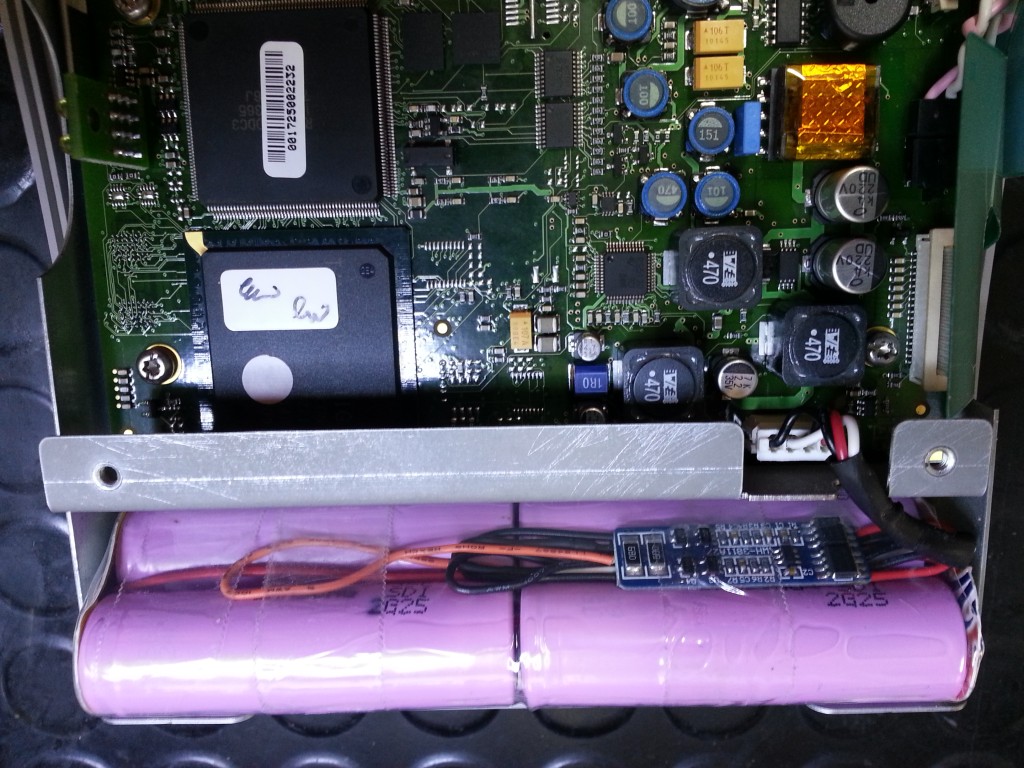
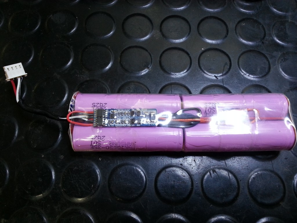
To solve that I decided to install a Li-Io battery with protection board. Apart from a better Li-Io life cycle these batteries double the capacity with a lower cell count. Original 6S1P 3200mAh NiMH replaced by 2S2P 7000mAh Li-Io type 18650 cells. 2S2P means two cells in parallel with another two cells in series.

A four cell pack of 18650 type Li-Io batteries fits nicely into the FSH6 battery bay. I used the original wiring harness that connects the battery to main PCB. It includes a temperature sensor that is required to keep the FSH6 running. Two black wires and the temperature senors open end connect together to ground on the battery protection board. Red wire goes to positive output on protection board.

Battery protection board is a cheap one from eBay and includes protection against short/high current, under voltage and over voltage. Important feature is the under voltage protection that prevents deep discharge of cells. The battery cells will be disconnected from load (= FSH6 standby mode) until next charge cycle.
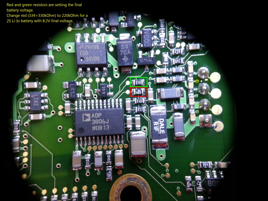
Charging the Li-Io battery is simple since the FSH6 includes already a charging circuit based on ADP3806 that is capable of Li-Io chemistry. The battery pack will be charged in CC/CV mode as required. The only modification required is for final battery voltage by replacing a single SMD resistor.
A few facts about the charging/power supply circuit:
- Low battery shut-off at 6.2V
- NiMH Charge voltage 10V, current up to 1A
- Charging occurs only when device is in standby (off)
- According to service manual battery will not be charged when device is turned on!?
- External power supply 18V/0.8A

The ADP3806 sets the final battery voltage by two resistors. Marked red and green in image above. Original these are 330kOhm and 100kOhm. In datasheet linked below these are R11 and R12 in schematic on page 11. This page describes the calculation of the final battery voltage from these two resistors. With 330kOhm and 100kOhm that results in a ratio of 3.3 or a final battery voltage of 10.75V, which is close to the 10V I have measured.
For a two series cell Li-Io battery pack the final voltage needs to reduced below 8.2V. So I replaced the 330kOhm resistor with 220kOhm. Resulting in a ratio of 2.2 or final battery voltage of 8V, measured 8.05V in reality. That's sufficient for the Li-Io battery pack to be considered full charged.
Still need to perform a long term test for run time but the modification looks promising.
👈 Home
