
LT3652 Solar Cell MPPT
Maximum power point tracking (MPPT) is a technique that solar battery chargers and similar devices use to get the maximum possible power from one or more solar panels (several solar cells connected in series and parallel). Solar cells have a complex relationship between solar irradiation, temperature and total resistance that produces a non-linear output efficiency known as the I-V curve. It is the purpose of the MPPT system to sample the output of the cells and apply the proper load to obtain maximum power for any given environmental conditions.
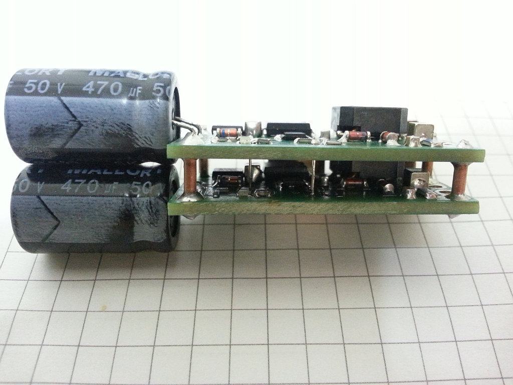
The following solar battery charger circuit is based on a LT3652 from Linear Technology. It's simple design just based on the data sheet and application notes. Another advantage apart from simplicity is the fact the board using the LT3652 can be stacked in parallel and therefore provide more output power if the solar panel can handle it.
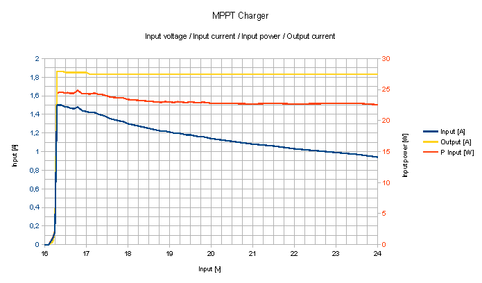
My circuit is designed to charge a LiPo battery in 3S configuration with a current of max 2A out of a 36 series cells solar panel providing a nominal voltage of ~18V. The output provides a constant current or constant voltage to the battery depending on the charging state.
A plot showing the input and output current as well as input power under ideal conditions:
PCB is double sided with only one side populated while the other one serves as heat sink. A exposed pad on the bottom side (just below the LT3652) can be used to attach the board to a separate heat sink.
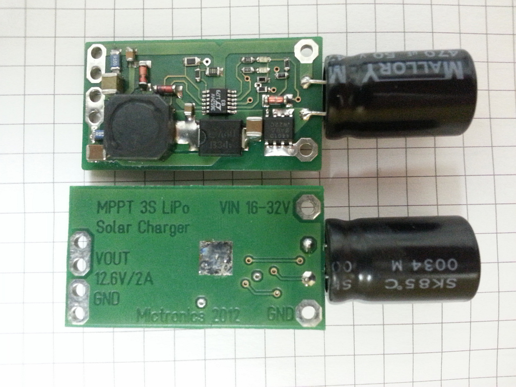
Visible are the connections between input and output and in the middle two extra connections for input reference voltage and output voltage feedback. Basically one board provides these two voltages for all others stacked to this one. In other words a master board driving several slave boards.
My design uses a P-channel MOSFET instead of a Schottky diode to protect the solar panel from reverse currents. This trick minimizes the voltage drop on the protection circuit to <10mV compared to a diode with roughly 400-600mV. Efficiency of the circuit increases this way.
Two LEDs indicating the status of the charger board. A green LED indicating the charging status when the board is suppling more than 1/10 of the programmed charging current. The second red LED indicates any faults which can be over temperature, internal charging timer overflow or battery fault.
Useful design documents:
LT3652 Development Board
LTJournal-V20N4-02-df-LT3652-Jay_Celani
LT3652 Datasheet
LTMag-V19N4-04-LT3652-JimDrew
Schematic
BOM
Schematic Input 15V/Output 7.2V
BOM 7.2V
Schematic Input 18V/Output 14.2V
BOM 14.2V
👈 Home